|
|
Access Control
This tab allows you to configure Access related settings of the Device.
Screen Layout of Access Control
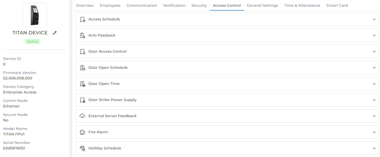
Field Description of Access Control
It contains various sections to save respective settings. Click on the particular section to expand it.
This section allows users to enable Access Schedules on the selected Device. A list of Access Schedules created from Company Schedule >> Access Schedule section along with default Schedules ("No Access" and "Full Access") will be displayed.
|
NOTE Access Schedules will be displayed only if they have been sent to the selected Device from Company Schedule >> Access Schedule section.
|
Click on the switch to turn Access Schedule feature ON or OFF. Turn the feature ON to enable the Access Schedules on the Device. Following options will be enabled when the feature is turned ON -

Click on ► icon in the first column of each Schedule to expand and view that Schedule.
To delete a Schedule, select it by clicking on its row and then click on Delete button to delete that particular Schedule from the Device. Please note that a Default Schedule can not be deleted.
Once entered, click on APPLY button to save and apply the settings.
Click on RESET button to restore the original settings.
Anti-Passback is a security mechanism that prevents a card holder from passing their card back to a second person to enter the same controlled area. It's a technique used to prevent a card gaining access to an area without first having exited that area. The Anti-Passback feature sets a specific sequence in which the Employee’s credentials must be used for the system to grant access. IXM Devices allow for programming of Entry and Exit parameters.
Click on the switch to turn Anti-Passback feature ON or OFF. Following options will be enabled when the feature is turned ON -

SETTINGS
Device Type:
Device can be configured as an Entry (IN) or an Exit (OUT) Device type. Entry (IN) Device type remembers the anti-passback status of each card in the system, the three possibilities being that the card is currently “IN” or “OUT” or its status is undefined.
Click on the box to select Device Type as either "Entry (IN)" or "Exit (OUT)" from the dropdown list.
Re-enter Delay(sec):
Enter the minimum duration between Entry (IN) and Exit (OUT).
When a card enters an Anti-Passback area, it will be removed and deemed to be of unknown whereabouts by the system after the delay has passed. For example, an entry of 60 seconds would cause a Card to be returned to the unknown state one minute after entering the area. The Employee will be able to set the delay between (0-1800) seconds.
Mode:
Click on the box to select the Mode from the dropdown list.
"Strict" anti-pass-back mode restricts the entry with logs. "Soft" anti-pass-back mode allows the re-entry but maintains the log.
Forgiveness

This option will be enabled only if Mode is selected as "Strict" and Device Type is selected as "Entry (IN)".
Forgiveness time is used to clear all cards from an Anti-Passback area at a specific time of each day. At the Forgiveness time, any card present within an Anti-Passback area is removed and deemed to be of unknown whereabouts by the system. The next use of a Card at any Device associated with the Anti-Passback area will place it back into the correct side of the Anti-Passback area.
Duress Status

This option will be enabled only if Mode is selected as "Strict". Click on the box to enable or disable Duress Status feature. A check mark in the box indicates the feature is enabled.
When Duress Status is active, it will allow Employee to pass, when they use one of their duress fingers.
Start Time:
Enter time when Forgiveness / Duress Status starts.
End Time:
Enter the time when Forgiveness / Duress Status ends.
Once entered, click on APPLY button to save and apply the settings.
Click on RESET button to restore the original settings.
|
|
MYCRO, MERGE & MERGE CR Devices are equipped with an internal relay (Max rating 1A @ 24VDC) which can be used for standalone Door Access Control for a single door.
TITAN, TOUCH 2, TFACE & SENSE 2 Devices are equipped with an internal relay (Max rating 2A @ 24VDC) which can be used for standalone Door Access Control for a single door.
There are two ways to configure the Door Access Control settings of IXM Devices:
-
Configuring Door Access Control (DAC) from IXM WEB.
-
From the TITAN, TFACE and TOUCH 2 LCD menu.
Click on the switch to turn Door Access Control feature ON or OFF. Following options will be enabled when the feature is turned ON -
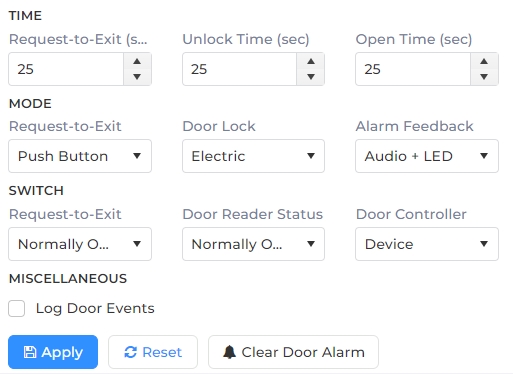
TIME
Request-to-Exit (sec):
Enter the time duration in seconds.
It indicates the time from activation of the Request-to-Exit trigger until the door is opened. If the door is not opened within this time, the door lock will return to the LOCKED state. If the door is open beyond the time duration, then the “Door Forced Open” alarm will activate.
Unlock Time:
Enter the time duration in seconds.
It indicates the time immediately following a biometric authentication until the door is open. If the door is not opened within this time, the door lock will return to the LOCKED state. If the door is open beyond the time duration, then the “Door Forced Open” alarm will activate.
Open Time:
Enter the time duration in seconds.
It indicates the time duration to allow the door to remain open. If the door is open beyond the time duration, then the “Door Open Too Long” alarm will activate.
MODE
Request-to-Exit Mode:
Select the Mode of Request-to-Exit from the dropdown list. There are three options:
Push Button
Motion Detector
None
Door Lock Mode:
Select the Mode of Door Lock from the dropdown list. There are two options:
Electric
Manual
Alarm Feedback Mode:
Select the Mode of Alarm Feedback from the dropdown list. There are three options:
Audio
LED
Audio + LED
SWITCH
Request-to-Exit:
Select the switch from the dropdown list to determine whether the door needs to open or close upon user authentication. There are two options:
Normally Closed
Normally Open.
Door Reader Status:
Select the switch from the dropdown list to determine whether the door contact status is open or closed. There are two options:
Normally Closed
Normally Open.
Door Controller:
Select the switch from the dropdown list to determine whether Door Access Control settings will be controlled by the IXM Device or the secure relay box.
MISCELLANEOUS
Log Door Events
Click on the checkbox to enable or disable this feature. A check mark in the box indicates the feature is enabled. By default, this feature is disabled.
Enabling this feature will log the door events such as "Door Open" and "Door Closed" in the Transaction Logs.
Disabling this feature will not log the door events in the Transaction Logs.
Once entered, click on APPLY button to save and apply the settings.
Click on RESET button to restore the original settings.
Click on Clear Door Alarm button to disable the alarm generated during normal operation. A “Door Force Open Alarm cleared” message will be displayed.
|
NOTE You can also configure Door Access Control from the Device LCD. Read more... |
Activating the Door Open Schedule feature will trigger an override of the IXM Device’s relay and alarm to allow Employees to open the door without providing access credentials (biometric, card, or ID) based on the specified schedule.
Click on the switch to turn Door Open Schedule feature ON or OFF. Following options will be enabled when the feature is turned ON -
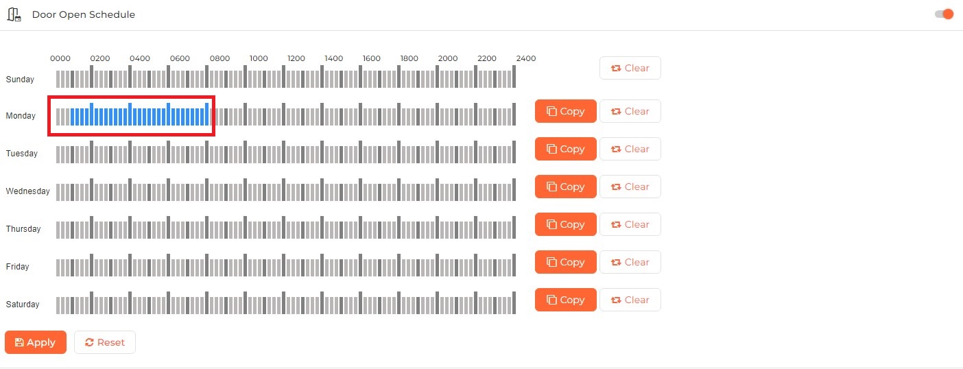
A schedule is created by clicking, holding, and dragging the cursor across the desired time duration as shown in red.
Click on Copy button in any blank row to replicate the selected duration.
Click on Clear button to clear the selected duration in that row.
Once entered, click on APPLY button to save and apply the settings.
Click on RESET button to restore the original settings.
Activating the Door Open Time feature will trigger an immediate override of the IXM Device’s relay and alarm to allow Employees to open the door without providing access credentials (biometric, card, or ID) for a specified duration in minutes (max 1439 min) & seconds (max 59 sec).
|
NOTE Door Access Control should be enabled to configure Door Open Time.
|
Click on the switch to turn Door Open Time feature ON or OFF. Following options will be enabled when the feature is turned ON -

Enter the Door Open duration in minutes and seconds.
Once entered, click on APPLY button to save and apply the settings. As a result, for the specified duration of Door Open Time, the IXM Device will sound a continuous tone. Upon refresh of the web browser, the status of the IXM Device will update from “ONLINE” to “DOT” as shown below.
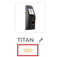
To immediately override the IXM Device’s relay and alarm to allow for Employees to open the door without providing access credentials (biometric, card, or ID) for a 10-second interval, click the Open Door button near Device Status.


Click on RESET button to restore the original settings.
|
NOTE You can also configure Door Open Time from the Device LCD. Read more... |
TITAN, TFACE, TOUCH 2 & SENSE 2 are equipped with the ability to redirect all their extra power and use it to supply to the Electric Door Strike, removing the need to have 2 separate power sources - 1 for the device and 1 for the door strike. Activating the Door Strike Power Supply feature will trigger a specified power supply to the connected strike.
There are two ways to configure the Door Strike Power Supply settings:
-
Through IXM WEB application
-
From TITAN, TFACE, and TOUCH 2’s Device LCD
To enable this feature, the Door Access Control wiring is different compared to using 2 separate power supplies.
|
NOTE Please refer to the respective wiring diagram in the INGUIDE or the installation guide before configuring this setting in IXM WEB. |
Click on the switch to turn Door Strike Power Supply feature ON or OFF. Following option will be enabled when the feature is turned ON -
Mode:
Change the Mode value to 12V or 24V depending on the installed door strike specifications. (TOUCH 2 and SENSE 2 only support a 12V door strike).
Once entered, click on APPLY button to save and apply the settings.
Click on RESET button to restore the original settings.
|
NOTE You can also configure Door Strike Power Supply from the Device LCD. Read more... |
External Server Feedback Authentication Servers will perform additional validation (e.g. shifts, medical, visa, license, etc.) from their end and then send a response and message to IXM Devices.
IXM Devices will then show Access Granted and display the message received from the server. This will be displayed as a pop-up message on the Device with a configurable message timeout.
IXM Devices should show access denied with an appropriate message as received by Example: Access Denied, Message: “Medicals Expired “, “Contract Over”. This will be displayed as a pop-up message on the Device with a configurable message timeout.
Click on the switch to turn External Server Feedback feature ON or OFF. Following options will be enabled when the feature is turned ON -

IP Address:
Enter the IP Address for connecting to External Server Utility. IP Address should be the same as the IP Address of External Server Utility.
Port:
Enter the Port for connecting to External Server Utility. Port should be the same as the Port of External Server Utility.
Response Timeout:
Enter the timeout duration for response.
Enable Offline Authentication
Click on the checkbox to enable or disable Offline Authentication mode.
Mentioned below is the result table for your reference:
| Offline Authentication | Saco Server Result | Result |
| Enable | Connected and get data | The Device will display the same server data |
| Enable | Not reachable/Time out | The Device will display access granted default screen of the Invixium Device |
| Disable | Connected and get data | The Device will display the same server data |
| Disable | Not reachable/Time out | The Device will display server timeout (Access Denied) |
Once entered, click on APPLY button to save and apply the settings.
Click on RESET button to restore the original settings.
|
NOTE You can also configure External Server Feedback from the Device LCD. Read more... |
The Fire Alarm is an emergency event occurring when the smoke or fire detector detects a fire condition. In case of such an event, the Fire Alarm feature will provide input to the Invixium Device to take the required action. IXM WEB allows the users to activate or deactivate the fire alarm setting on the Device.
Hardwire Connections
The fire alarm connections are highlighted below and can be located on the top connector of the wiring harness of the Invixium Device.
|
NOTE Invixium recommends the use of all the ground wires. |
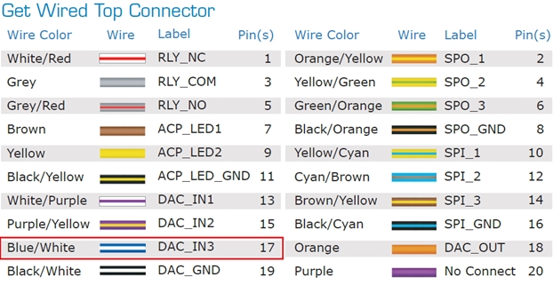
The DAC IN3 wire will be connected with the Fire Panel Controller’s wiring harness. When a fire panel senses fire, it triggers the fire alarm in the Device. The Device then opens the door in the situation of a fire alarm using the door access control settings.
Following option will be displayed:
Status
Click on the checkbox to enable or disable the Status of Fire Alarm on the Device.
Once entered, click on APPLY button to save and apply the settings.
Click on RESET button to restore the original settings.
Click on CLEAR & RE-ACTIVATE button to clear and reactivate the Fire Alarm if the Status is enabled.
This section allows users to view Holiday Schedules created from Company Schedule >> Holiday Schedule section.
|
NOTE Holiday Schedule will be displayed only if they have been sent to the selected Device.
|
A list of Holiday Schedules sent to the selected Device will be displayed as follows:

Click on ► icon in the first column of each Schedule to expand and view that Schedule.
To delete a Schedule, select it by clicking on its row and then click on Delete button to delete that particular Schedule from the Device.
IXM WEB allows users to manage / configure Input and Output changes on IXM Devices.
Hard Wire Connections
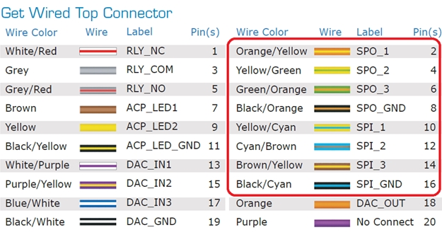
The SPIO connections are highlighted below and are located on the Top Connector of the Wiring Harness of the IXM Devices.
|
NOTE Invixium recommends the use of all the ground wires. |

|
The number of SP Input varies depending on the Device. For information please visit Invixium.com and refer the Datasheet for the required Device from the Downloads section. |
The following options will be displayed:
INPUTS
Event:
Select the Event from the dropdown list. Following Events are supported -
None
Device will not take any action.
Release alarm
Any alarm signal triggered will be cleared.
Restart Device
The Device will be restarted.
VoIP Call

Supported in SENSE 2, TOUCH 2, TFACE, and TITAN Devices only.
The Device will establish a VoIP call with configured VoIP contact.
Door Open
The door will be opened. This even will take place only if the Door Access Control feature is enabled and configured from Devices >> Access Control >> Door Access Control section.
Camera Open

Supported in TFACE, and TITAN Devices only.
The camera will be opened on the Device if this event is configured.
Action:
Select the Action when the Event is triggered from the dropdown list. Following Actions take place -
Falling edge
Input pulse edge will be lowered.
Rising edge
Input pulse edge will be raised.
Duration:
Enter the duration between the two input pulses. It should be between 10 and 2000 milliseconds.
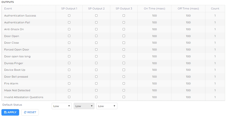
OUTPUTS
IXM WEB allows users to choose various SP Output events, On Time, Off Time and Counter value which will be generated for specific events. Specific purpose output generates a pulse from 10 to 2000 milliseconds for On time and from 10 to 2000 milliseconds for Off time, with 0 to 100 counts. Pulse can be generated based on events occurring on the IXM Device. Specific purpose output can support the following event triggers:
Event:
Select the Event from the dropdown list. Following Events are supported -
Authentication Success
On successful authentication, the Device will send an output pulse.
Authentication Fail
On failed authentication, the Device will send an output pulse.
Anti-shock On
When an Anti-Shock event triggers the Device will send an output pulse.
Door Open
When a door opens, the Device will send an output pulse.
Door Close
When a door closes, the Device will send an output pulse.
Door Open too long
When the door is open for long duration, the Device will send an output pulse.
Duress Finger
When an Employee authenticates using duress finger the Device will send an output pulse.
Device Boot Up
When the Device boots up, the Device will send an output pulse.
Fire Alarm
When fire alarm triggers the Device will send an output pulse.
SP Output 1:
Click on the checkbox to enable first SP Output line. It will allow the pulse to pass on the first SPO line.
SP Output 2:
Click on the checkbox to enable second SP Output line. It will allow the pulse to pass on the second SPO line.
SP Output 3:
Click on the checkbox to enable third SP Output line. It will allow the pulse to pass on the third SPO line.
On Time (msec):
Enter On time duration (10 to 2000 milliseconds) of a pulse generated for selected events.
Off Time (msec):
Enter Off time duration (10 to 2000 milliseconds) of a pulse generated for the selected event.
Count:
Pulse will be generated for the value (0 to 100) provided in this field.
Default Status:
Select the Default Status from the dropdown list when SP Output line is generated on an IXM Device which are as follows:
Low Level
High Level
Once entered, click on APPLY button to save and apply the settings.
Click on RESET button to restore the original settings.
|
|
OSDP is a more secure connection method compared to the traditional Wiegand communication interface.
OSDP utilizes two-way encrypted communication that makes it immune to being eavesdropped, faked or bypassed. OSDP flags tampering or disconnection right away. Furthermore, OSDP establishes a Secure Channel Protocol which is essential for exchanging secure credentials such as digital keys.
Click on the switch to turn OSDP feature ON or OFF. Following option will be enabled when the feature is turned ON -

COMMUNICATION SETTINGS
Baud Rate:
It denotes the Baud Rate of serial communication. The value has to be the same as the Access Control Panel’s value.
Parity Bit:
It denotes the Parity Bit of the serial communication. The value has to be the same as the Access Control Panel’s value.
Stop Bit:
It denotes the Stop Bit of the serial communication. The value has to be the same as the Access Control Panel’s value.
Timeout (msec):
Enter the time duration (500 to 10000 milliseconds) up to which the Device should keep trying to connect to the Access Control Panel. The default timeout duration is 300 milliseconds. On timeout, the Device LCD flashes "Access Denied" message and the “Application Logs” window will show a failure message.
GENERAL SETTINGS
Enable Log
Click on the checkbox to enable or disable the feature. A check mark in the box indicates that the feature is enabled.
Enabling this feature logs OSDP events for support and debugging purposes.

Invixium recommends disabling this feature unless needed.
Display OSDP Text
Click on the checkbox to enable or disable the feature. A check mark in the box indicates that the feature is enabled.
Enabling this feature will display OSDP Text.
SmartCard Passthru
Click on the checkbox to enable or disable the feature. A check mark in the box indicates that the feature is enabled.
When presenting a smart card, the Device passes the smart card CSN to Access Control Panel without taking any other action.
Enable Biometric
Click on the checkbox to enable or disable the feature. A check mark in the box indicates that the biometric template verification is enabled.
SECURE CHANNEL
Secure Key:
The secure key is provided by your Access Control Panel most of the time. However, provisions for manual entry can be added as TEXT or HEX.
VISITOR
Enable OSDP
Click on the checkbox to enable or disable the feature. Enabling this feature will send Card details to the Access Control Panel even if the card is not assigned to any employee on the device. Based on the response from the Access Control Panel; the device will display “Access Granted” or “Access Denied”.
OSDP EVENTS
Events:
The OSDP static events for panel feedback are:
Access Granted
Access Denied
Enter PIN
Dual Authentication - It is an access mode which requires valid access by two authorized cardholders to enter an access zone within a specified time period. This feature is available only if Multi-User Authentication feature is enabled and configured from Devices >> General Settings >> Multi-User Authentication section. On enabling this feature, the following actions will be performed:
The Device will request for the credentials of the second user after the first user is authenticated successfully.
Card numbers for both, the first and the second user will be transferred to the Access Control Panel.
Two events, one for the first user and the other for the second user will be logged into the Access Control Panel.
On Color/Off Color:
Click on the box to select Color from the dropdown list.
Select the LED color configuration based on the panel event. The value has to be the same as the Access Control Panel’s value. Options are:
Red
Green
Yellow
Blue
NOTE Mismatch between the unit and Access Control Panel LED configuration would cause unrecognized events.
On Time/Off Time:
Enter the LED timing configuration based on the panel event. The value has to be the same as the Access Control Panel’s value.
NOTE Mismatch between the unit and Access Control Panel LED timing configuration would cause unrecognized events.
Display Message:
Click on the checkbox to enable or disable Notification on the Device’s screen.
When enabled, this feature displays both the unit hard coded notification and the Access Control Panel notification as follows -
IXM notification - "Access Granted or Access Denied"
Access Control Panel notification - "Valid or Invalid"
When disabled, this feature displays only the Access Control Panel notification.
Once entered, click on APPLY button to save and apply the settings.
Click on RESET button to restore the original settings.
IXM Devices can be deployed in a full access control installation and include direct connections to any access control panel. In such an installation, the authentication cycle can be considered a two-stage process where the first is (a) physical authentication at the IXM Device level which automatically triggers the second (b) authentication at the panel level. Given the two-stage process, some installations require the LED indicators on the IXM Device to report the result of the authentication attempt after the second stage. This requires the LEDs on the IXM Device to be controlled by the panel. IXM Devices allow for LED control by the panel if the functionality is available on the panel.
This feature is called Panel Feedback and requires the following:
-
Hardwire connections to the wiring harness of the IXM Device.
-
Configuration of the panel feedback settings in IXM WEB.
Hardwire Connections
The panel feedback connections are highlighted below and can be located on the top connector of the wiring harness of the MYCRO, TOUCH 2, and SENSE 2 Devices. The corresponding outputs from the panel should be connected to these wires for LED control by the panel.
|
NOTE INVIXIUM recommends the use of all ground wires. |
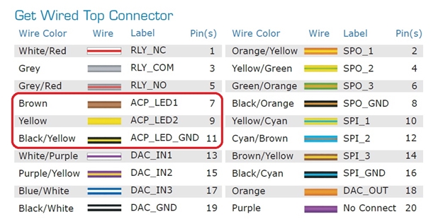
The panel feedback connections are highlighted below and can be located on the bottom connector of the wiring harness of the TITAN Device.
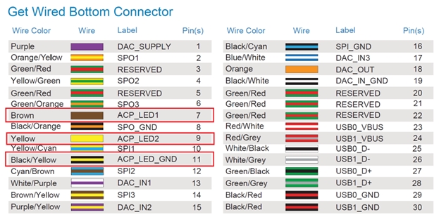
The panel feedback connections are highlighted below and can be located on the bottom connector of the wiring harness of the TFACE Device.
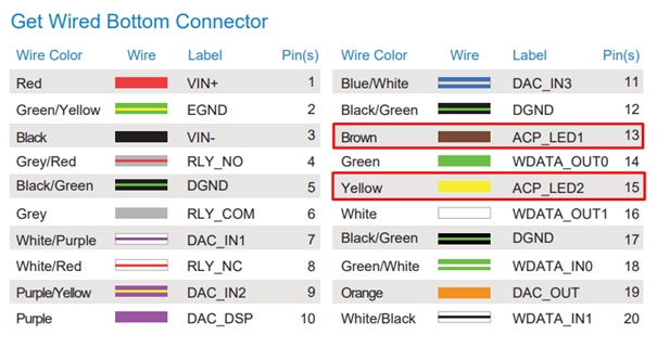
Click on the switch to turn OSDP feature ON or OFF. Following option will be enabled when the feature is turned ON -
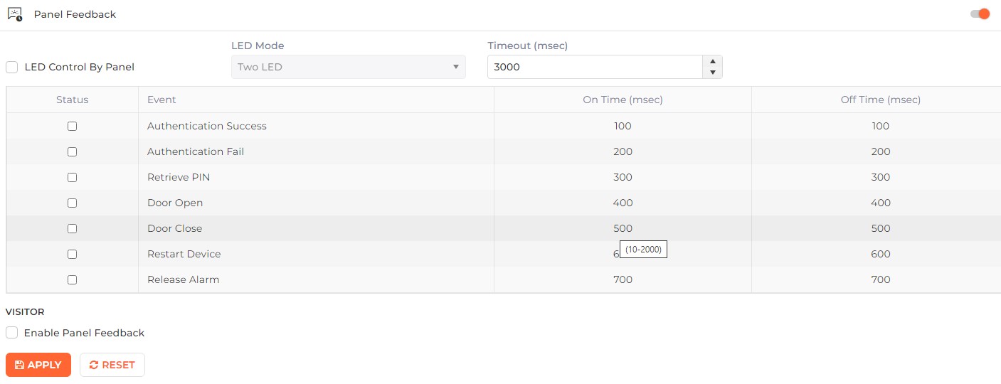
LED Control By Panel
Click on the checkbox to enable or disable the feature. A check mark in the box indicates that the feature is enabled.
If enabled, the LEDs on the IXM Device will be controlled by the panel.
LED Mode:
Click on the box to select LED Mode from the dropdown list.
Selecting “One LED” mode will allow the panel to turn the LEDs on the IXM Device either GREEN (Access Granted) or RED (Access Denied), which requires one wire connection. Selecting “Two LED” mode will allow the panel to turn the LEDs on the IXM Device either OFF, GREEN (Access Granted), RED (Access Denied), or AMBER (Alarm), which requires two-wire connections.
Timeout:
Enter Timeout for event detection (500 ms to 10000 ms). The Device must receive feedback from the panel within the timeout period.
Enable Pulse Processing

|
This option is displayed only when LED Control By Panel is enabled. |
Click on the checkbox to enable or disable the feature. A check mark in the box indicates that the feature is enabled.
If enabled, the IXM Device will display LED based on the “Pulse Processing Time” and “LED Driven Mode”.
LED Driven Mode:

|
This option is enabled only when Enable Pulse Processing is enabled. |
Click on the box to select “Low” or “High” options as per the requirement.
Pulse Processing Time:

|
This option is enabled only when Enable Pulse Processing is enabled. |
Configure pulse processing time as per the requirement.
Next, a list of Events will be displayed as follows -

Event:
Click on the checkbox to enable the respective event for which the Panel will take control of the LEDs on the IXM Device (only if the triggering of the event is supported by the panel). Following are the events -
-
Authentication Success
-
Authentication Fail
-
Retrieve PIN
-
Door Open
-
Door Unlock
-
Restart Device
-
Release Alarm
On Time (msec):
Enter On time (10 to 2000 Milliseconds) of pulse generated by panel for the selected event.
Off Time (msec):
Enter Off time (10 to 2000 Milliseconds) of pulse generated by panel for the selected event.
Once entered, click on APPLY button to save and apply the settings.
Click on RESET button to restore the original settings.
|
|
This feature enables security personnel to adjust security levels in response to a perceived threat. It allows administrators to change the access rule (authentication level) of the Invixium device (TITAN) using input received to the device.
Click on the switch to turn the Threat Level feature ON or OFF. The following options will be enabled when the feature is turned ON:

Mode:
Select the Mode of Threat Level from the dropdown list. IXM WEB supports three modes of Threat Level:
-
Static
-
Schedule
-
GPIO (General Purpose Input Output)
Level:

|
This option will be disabled when the Mode is selected as “Schedule” or “GPIO”. |
Select the applicable Threat Level for the device from the dropdown list.
Enable Duress:
Click on the box to enable or disable the Duress feature for Threat Level. A checkmark in the box indicates the feature is enabled.
Enabling the "Duress" feature ensures that employees follow the threat level even when they use a duress finger.
When the “Enable Duress” feature is disabled, all the duress fingerprints will be bypassed for the Threat Level.
INPUTS

|
This option will be disabled when the Mode is selected as “GPIO”. |
-
When the Mode is set to "GPIO," the three SP input lines will be utilized for handling input Threat Levels.
-
You can define Threat Levels for four different GPIO configurations.
-
When the Mode is set to “GPIO”, the Input lines cannot be utilized, and the INPUT section will remain disabled.
Select the Threat Level for each input combination from the dropdown list, For the hardware input combination, refer to the hardware section.

Once entered, click on the APPLY button to save and apply the settings. Click on the RESET button to restore the original settings.
This section displays the Threat Level Schedule of the Device as follows:
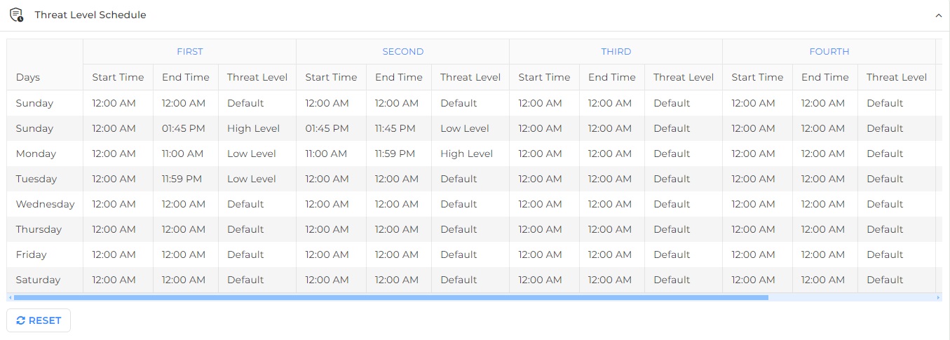
Click on the RESET button to restore the original settings.
IXM Devices have provisions to allow for other Wdiegand Devices (i.e. External card readers) to be connected to the system and provide signals for Wiegand Input.
Utilizing the Wiegand Input feature requires the following:
1. Hardwire connections to the Wiring Harness of the IXM Device.
2. Configuration of the Wiegand Input settings in IXM WEB.
The Wiegand Input settings in IXM WEB support up to 5 Wiegand formats, Wiegand PassThru, and Cards Passthru functions.
There are two predefined Wiegand Formats set up by default:
-
Standard 26-bit
Standard 26-bit Wiegand format will be able to Activate or Deactivate Verify Facility Code.
-
IXM 42-bit EM Prox
IXM 42-bit EM Prox format will be able to select Prox Card mode options as 3-byte Numbers & 5-byte Numbers.
Hard Wire Connections
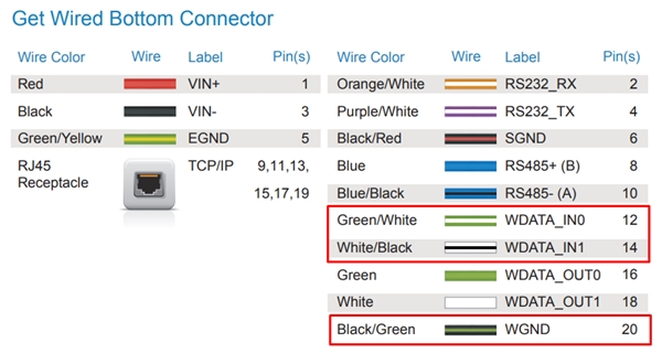
The Wiegand Input connections are highlighted below and are located on the bottom connector of the wiring harness of MYCRO, SENSE2, TOUCH2 & MERGE2 Series.
|
NOTE INVIXIUM recommends the use of all ground wires. |
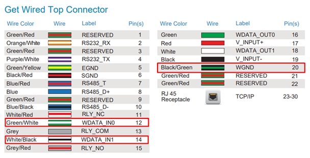
TITAN Device Wiegand Input connections are highlighted below and are located on the top connector of the wiring harness.
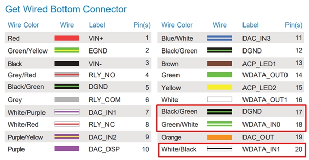
TFACE Device Wiegand Input connections are highlighted below and are located on the bottom connector of the wiring harness.
Click on the switch to turn Wiegand Input feature ON or OFF. Following option will be enabled when the feature is turned ON -

Verify Facility Code
Click on the checkbox to enable or disable the feature. A check mark in the box indicates that the feature is enabled.
Enable if you want the Facility Code Verified.
Exit Reader
Click on the checkbox to enable or disable the feature. A check mark in the box indicates that the feature is enabled.
Enable if this Device will be used as an Exit Reader.
PASSTHRU MODE
Passthru:
Click on the box to select Passthru from the dropdown list. Following are the Passthru Modes -
None
Passthru mode will not be applicable.
Wiegand
Selection of Wiegand Passthru will send all bits of the Wiegand string.
Cards
Selection of Cards Passthru mode will send all bits of the Card Serial Number (CSN).
INPUT WIEGAND FORMAT
Card Type:
Click on the box to select the Card number from the dropdown list.
Format:
Click on the box to select one of the predefined Wiegand formats or Custom formats uploaded.
NOTE Custom and Passthru Wiegands are created through General Settings >> Wiegand option.
Once entered, click on APPLY button to save and apply the settings.
Click on RESET button to restore the original settings.
|
|
This option displays a list of Wiegands uploaded on the selected Device as follows -

Click on the x icon of the Wiegand box to delete that particular Wiegand. The application will display a warning message as follows -

Click on Delete button to remove the selected Wiegand permanently from the Device. The deleted Wiegand will also be removed from the list.
Click on Cancel button to discard the action.
IXM Devices can be deployed in a full access control installation and include direct connections to any access control panel. Wiegand protocol is the technology used for communication between IXM Devices and access control panels. The Wiegand interface involves 3 hardwires: DATA0, DATA1, and common ground. IXM Devices send out a Wiegand signal via these 3 wires to the Panel to report the status of the authentication attempt. The Wiegand Output signal can be configured for general or event-based output.
Setting up Wiegand Output requires the following:
-
Hardwire connections to the wiring harness of the IXM Device.
-
Configuration of the Wiegand Output settings for general and/or event-based parameters in IXM WEB.
Hardwire Connections
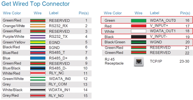
The Wiegand Output connections are highlighted below and are located on the bottom connector of the wiring harness for MYCRO, SENSE2, TOUCH2 & MERGE2 series. The corresponding Wiegand inputs to an access control panel should be connected to these wires.
|
NOTE INVIXIUM recommends the use of all ground wires. |
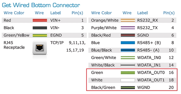
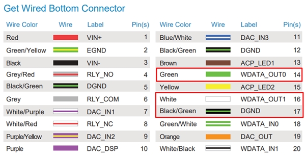
TFACE Device Wiegand Output connections are highlighted below and are located on the bottom connector of the wiring harness.
Click on the switch to turn Wiegand Output feature ON or OFF. Following option will be enabled when the feature is turned ON -
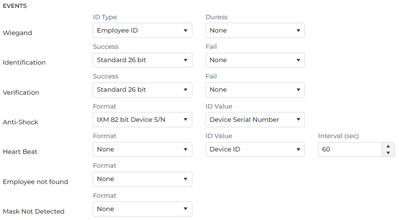
EVENTS
Wiegand
ID Type:
A Unique ID is provided to each Wiegand format. Select ID Type from the dropdown list.
Duress:
Select the Wiegand Format from the dropdown list.
Upon Duress authentication event, the selected Duress event will be sent over Wiegand output lines.
Identification Success
Success:
Select any predefined Wiegand format for the Identification Success event from the dropdown list.
Upon successful identification, the IXM Device will create a Wiegand string based on the selected Wiegand format. Employee ID/Prox card ID/Smart card ID will be used as Wiegand ID. This Wiegand string will be sent over Wiegand Output lines.
Fail:
Select any predefined Wiegand format for the Identification Fail event from the dropdown list.
Upon failed identification, the IXM Device will create a Wiegand string based on the selected Wiegand format, which will be sent over Wiegand output lines.
Verification
Success:
Select any predefined Wiegand format for the Verification Success event from the dropdown list.
Upon successful verification, the Device will create a Wiegand string based on the selected Wiegand format. Employee ID/Prox card ID/Smart card ID will be used as Wiegand ID. This Wiegand string will be sent over Wiegand Output lines.
Fail:
Select any predefined Wiegand format for the Verification Fail event from the dropdown list.
Upon failed verification, the Device will create a Wiegand string based on the selected Wiegand format. User ID/Prox card ID/Smart card ID value will be used as Wiegand ID. This Wiegand string will be sent over Wiegand Output lines.
Anti-Shock
Format:
Select any predefined Wiegand format for the anti-shock event from the dropdown list.
Upon an anti-shock alarm event, the Device will create a Wiegand string based on the selected Wiegand format. This Wiegand string will be sent over Wiegand Output lines. The default format for anti-shock is “IXM 82 bits device S/N”.
ID Value:
Select the Wiegand ID from the dropdown list.
Device ID / Device Serial Number / Device Name will be used as Wiegand ID.
Heart Beat
Format:
Select any predefined Wiegand format for the Heartbeat event from the dropdown list.
For a regular heartbeat pulse, the Device will create a Wiegand string based on the selected Wiegand format.
ID Value:
Select the Wiegand ID from the dropdown list.
Device ID / Device Serial Number / Device Name will be used as Wiegand ID.
Interval:
Enter the Interval.
This Wiegand string will be sent over Wiegand Output lines and repeated based on the selected Interval.
Employee Not Found
Format:
Select any predefined Wiegand format for the Employee Not Found event from the dropdown list.
Upon an “Employee Not Found” event, the Device will create a Wiegand string based on the selected Wiegand format. Entered Employee ID will be used as Wiegand ID. This Wiegand string will be sent over Wiegand Output lines.
Thermal Authentication
Format:
Select any predefined Wiegand format for the Thermal Authentication event from the dropdown list.
Upon an “Thermal Authentication” event, the Device will create a Wiegand string based on the selected Wiegand format. Entered Employee ID will be used as Wiegand ID. This Wiegand string will be sent over Wiegand Output lines.
Mask Not Detected
Format:
Select any predefined Wiegand format for the Mask Not Detected event from the dropdown list.
Upon an “Mask Not Detected” event, the Device will create a Wiegand string based on the selected Wiegand format. Entered Employee ID will be used as Wiegand ID. This Wiegand string will be sent over Wiegand Output lines.
Invalid Attestation Questions
Format:
Select any predefined Wiegand format for the Invalid Attestation Questions event from the dropdown list.
Upon an “Invalid Attestation Questions” event, the Device will create a Wiegand string based on the selected Wiegand format. Entered Employee ID will be used as Wiegand ID. This Wiegand string will be sent over Wiegand Output lines.
PULSE (MSEC)
Width (Wiegand Pulse Setting):
The width of the digital pulse of the Wiegand signal can be set between 20-2000 Microseconds.
Interval (Wiegand Pulse Setting):
The interval of the digital pulse of the Wiegand signal can be set between 200-20000 Microseconds.
Once entered, click on APPLY button to save and apply the settings.
Click on RESET button to restore the original settings.
|
|

